Register now for better personalized quote!

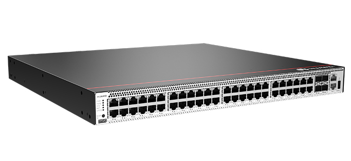
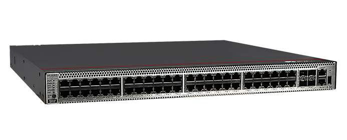
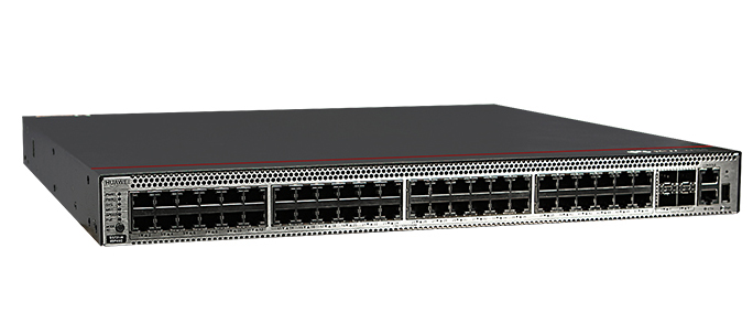
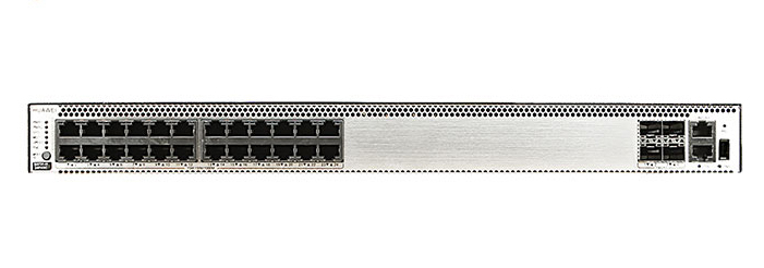
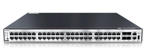
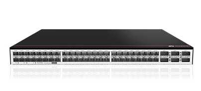
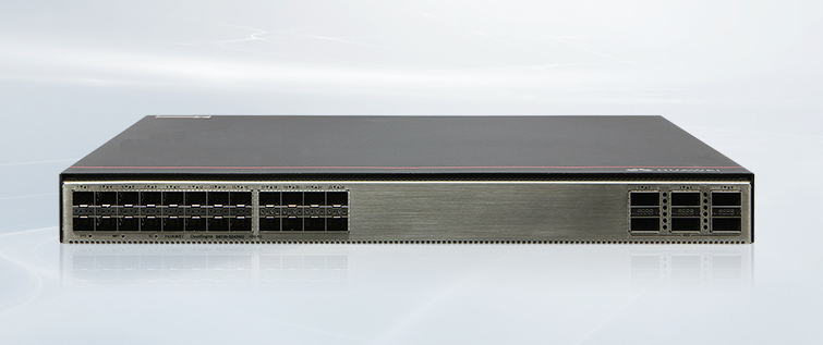
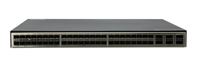
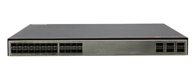
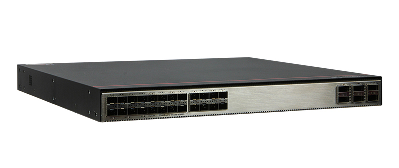

The Huawei S5731-S48T4X is a high-performance Layer 3 switch designed for enterprise networks. It offers advanced features, robust security, and efficient management, making it suitable for various networking scenarios.
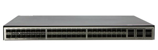
▪High Port Density:48 x 10/100/1000Base-T ports and 4 x 10GE SFP+ ports provide ample connectivity options.
▪Advanced Routing Capabilities:Supports static routes, RIP, OSPF, IS-IS, BGP, and more for flexible network configurations.
▪Enhanced Security:Features include MAC address filtering, port security, and various authentication methods to protect network integrity.
▪Efficient Management:Offers web-based NMS, SNMP, RMON, and intelligent O&M for streamlined network administration.
▪Energy Efficiency:Supports Energy Efficient Ethernet (EEE) and intelligent fan speed adjustment to reduce power consumption.
Fixed Ports: 48 x 10/100/1000Base-T, 4 x 10GE SFP+
Dimensions (W x D x H): 442 mm x 420 mm x 43.6 mm
Chassis Height: 1 U
Chassis Weight (including packaging): 8.55 kg
Power Supply Type: 150 W AC (pluggable), 600 W AC (pluggable), 1000 W DC (pluggable)
Rated Voltage Range: AC input (150 W AC): 100 V AC to 240 V AC, 50/60 Hz; AC input (600 W AC): 100 V AC to 240 V AC, 50/60 Hz; DC input (1000 W DC): -48 VDC to -60 V DC
Maximum Voltage Range: AC input (150 W AC): 90 V AC to 264 V AC, 47 Hz to 63 Hz; AC input (600 W AC): 90 V AC to 290 V AC, 45 Hz to 65 Hz; High-voltage DC input (600 W AC): 190 V DC to 290 V DC; DC input (1000 W DC): -38.4 V DC to -72V DC
Maximum Power Consumption: 124 W
Noise: Under normal temperature (sound power): 57.5dB (A); Under high temperature (sound power): 70.9dB (A); Under normal temperature (sound pressure): 47.5dB (A)
Operating Temperature: 0-1800 m altitude: -5°C to +45°C; 1800-5000 m altitude: The operating temperature reduces by 1ºC every time the altitude increases by 220 m.
Storage Temperature: -40℃ to +70℃
Relative Humidity: 5% to 95% (non-condensing)
Surge Protection (Service Port): Common mode: ±6 kV
Surge Protection (Power Port): AC power port: ±6 kV in differential mode, ±6 kV in common mode; DC power port: ±2 kV in differential mode, ±4 kV in common mode
Heat Dissipation: Air cooling heat dissipation, intelligent speed adjustment, and pluggable fans
▪MAC Address Table:Supports 32K MAC address entries with learning and aging capabilities.
▪VLAN Support:Accommodates up to 4094 VLANs with features like Guest VLAN, Voice VLAN, and VLAN mapping.
▪Loop Protection:Implements protocols like RRPP, Smart Link, and STP for network stability.
▪IPv6 Features:Offers comprehensive IPv6 support, including ACLs, MLD snooping, and DHCPv6.
▪Multicast:Supports IGMP snooping, PIM-SM, PIM-DM, and multicast load balancing.
▪QoS/ACL:Provides rate limiting, packet redirection, and advanced filtering for traffic management.
▪Security:Features include DoS attack defense, port isolation, MAC Forced Forwarding, and various authentication methods.
▪Reliability:Supports LACP, Ethernet OAM, BFD for various protocols, and more for network resilience.
▪VXLAN Support:Enables VXLAN L2 and L3 gateways with BGP-EVPN (license required).
▪Super Virtual Fabric (SVF):Supports a two-layer client architecture with plug-and-play capabilities.
▪iPCA:Provides real-time statistics on packet loss and network performance.
▪TWAMP:Measures two-way packet delay, one-way packet loss rate, and jitter.
▪Stacking:Supports iStack with up to 9 member switches for simplified management.
▪SNMP:Compatible with SNMP v1/v2c/v3 for network monitoring.
▪RMON:Provides remote monitoring capabilities.
▪Web-Based NMS:Offers a user-friendly interface for network management.
▪System Logs and Alarms:Facilitates troubleshooting with detailed logs and alerts.
▪Intelligent O&M:Enhances operational efficiency with smart management features.
The Huawei S5731-S48T4X is a versatile and robust switch that meets the demands of modern enterprise networks. Its comprehensive feature set, combined with efficient management and security capabilities, makes it an ideal choice for organizations seeking reliable network performance.
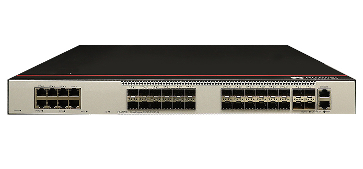
Huawei CloudEngine S5731-S48T4X Switches
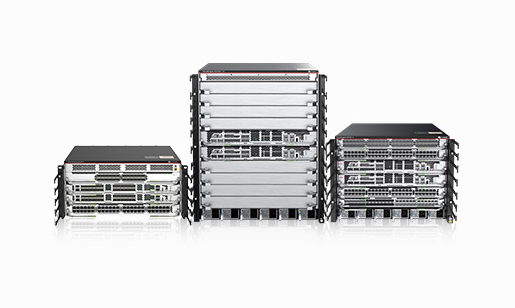
Huawei All Series Switches New and Used
For Huawei product list and quote, please visit: https://www.hi-network.com/categories/huawei or contact us at www.hi-network.com (Email: [email protected])
| Item | Details |
|---|---|
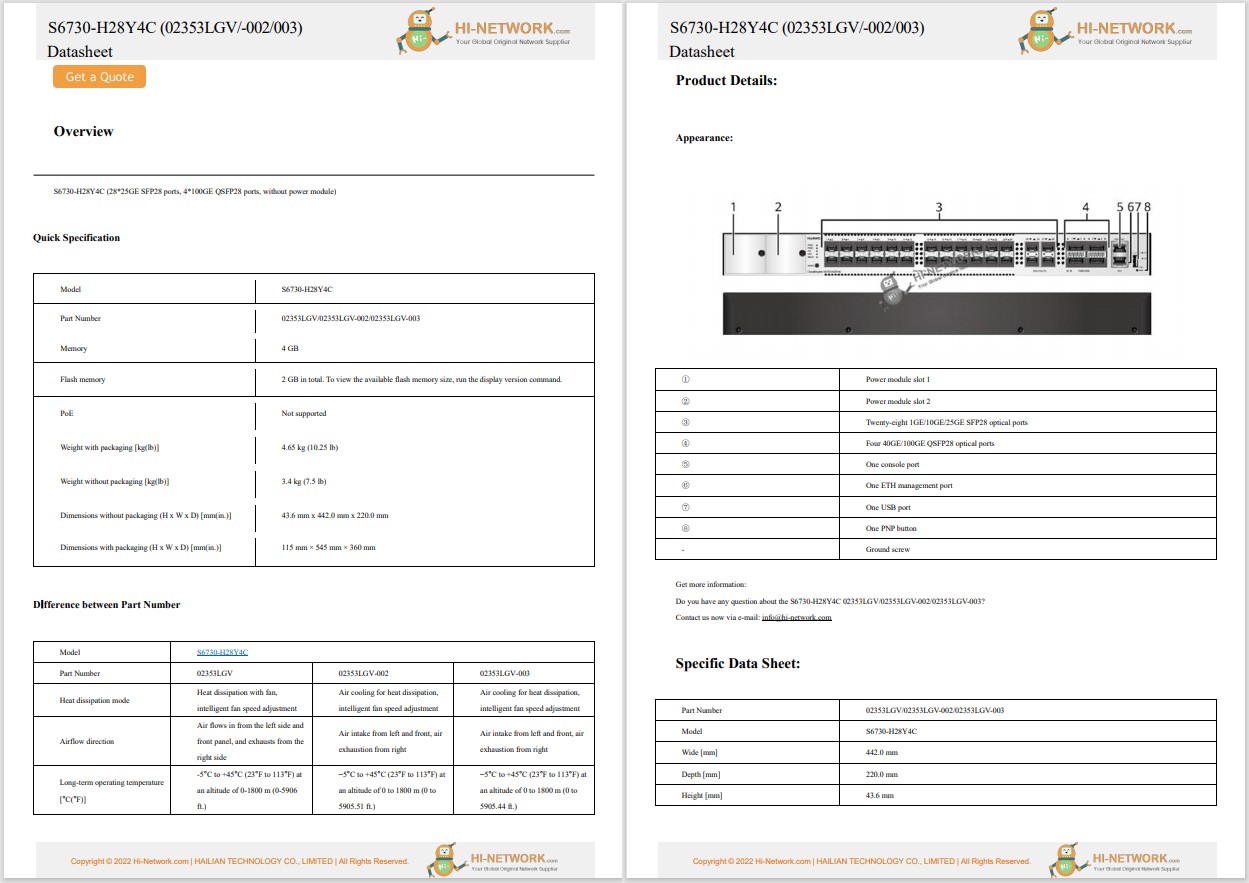
| Description | S5731-S48T4X (48*10/100/1000BASE-T ports, 4*10GE SFP+ ports, without power module) |
| Part Number | 98011847 |
| Model | S5731-S48T4X |
| First supported version | V200R021C10SPC600 |
| Supported Patch Version | If V200R021C10SPC500 is used, install V200R021HP0121 or a later patch. |

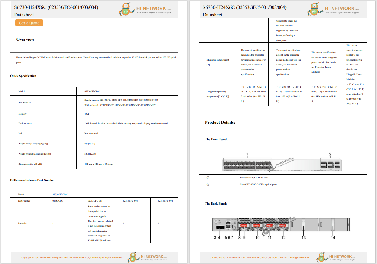
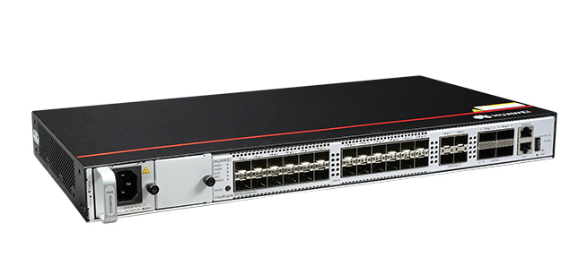
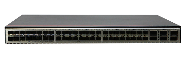
1 | Forty-eight 10/100/1000BASE-T ports | 2 | Four 10GE SFP+ optical ports |
3 | One console port | 4 | One ETH management port |
5 | One USB port | 6 | One PNP button NOTICE: To restore the factory settings and reset the switch, hold down the button for at least 6 seconds. To reset the switch, press the button. Resetting the switch will cause service interruption. Exercise caution when you press the PNP button. |
7 | Ground screw NOTE: It is used with a ground cable. | 8 | Power module slot 1 NOTE: Applicable power modules:
|
9 | Power module slot 2 NOTE: Applicable power modules:
| - | - |
| Port | Connector Type | Description | Available Components |
|---|---|---|---|
| 10/100/1000BASE-T port | RJ45 | A 10/100/1000BASE-T Ethernet electrical port sends and receives service data at 10/100/1000 Mbit/s. | Ethernet cable |
| 10GE SFP+ optical port | SFP+ | A 10GE SFP+ Ethernet optical port supports auto-sensing to 1000 Mbit/s. It sends and receives service data at 1000 Mbit/s or 10 Gbit/s. |
|
| Console port | RJ45 | The console port is connected to a console for on-site configuration. | Console cable |
| USB port | USB 2.0 Type A | The USB port can have a USB flash drive connected to upgrade the switch, or transfer configuration files or other files. The USB port can only connect to a USB flash drive that complies with USB 2.0. USB flash drives from different vendors differ in model compatibility and drivers. If a USB flash drive cannot be used, try to replace it with another one from a mainstream vendor. Switches support a maximum of 128 GB USB flash drives. | USB flash drive |
| ETH management port | RJ45 | You can connect a switch to a configuration terminal or network management workstation through the ETH management port to configure the switch locally or remotely. You can choose to download the software package through the ETH management port in the BootLoad menu. File transfer through the ETH management port is faster than transfer through the console port. | Ethernet cable |
The S5731-S48T4X has similar indicators to those on the S5731-S48P4X except that the S5731-S48T4X does not have a PoE mode indicator. For details, see the S5731-S48P4X.
The switch can use a single power module or two power modules for 1+1 power redundancy. Pluggable AC and DC power modules can be used together in the same switch. However, the power modules with fans and power modules without fans cannot be installed on the same switch.
The switch has two built-in fans for forced air cooling. Air flows in from the left, right, and front sides, and exhausts from the rear panel.

This figure only shows the airflow direction and does not depict the actual device.
| Item | Specification |
|---|---|
| Dimensions without packaging (H x W x D) [mm(in.)] | Basic dimensions (excluding the parts protruding from the body): 43.6 mm x 442.0 mm x 420.0 mm (1.72 in. x 17.4 in. x 16.54 in.) Maximum dimensions (the depth is the distance from ports on the front panel to the parts protruding from the rear panel): 43.6 mm x 442.0 mm x 448.0 mm (1.72 in. x 17.4 in. x 17.64 in.) |
| Dimensions with packaging (H x W x D) [mm(in.)] | 185.0 mm x 650.0 mm x 550.0 mm (7.28 in. x 25.59 in. x 21.65 in.) |
| Chassis height [U] | 1 U |
| Chassis material | Metal |
| Weight without packaging [kg(lb)] | 5.01 kg (11.05 lb) |
| Weight with packaging [kg(lb)] | 7.54 kg (16.62 lb) |
| Typical power consumption [W] | 78 W |
| Typical heat dissipation [BTU/hour] | 266.14 BTU/hour |
| Maximum power consumption [W] | 111 W |
| Maximum heat dissipation [BTU/hour] | 378.74 BTU/hour |
| Static power consumption [W] | 50 W |
| MTBF [years] | 73.81 years |
| Availability | > 0.99999 |
| Noise at normal temperature (acoustic power) [dB(A)] | 45.62 dB(A) |
| Noise at normal temperature (acoustic pressure) [dB(A)] | 31.94 dB(A) |
| Number of card slots | 0 |
| Number of power slots | 2 |
| Number of fans modules | 2 |
| Redundant power supply | 1+1 Pluggable AC and DC power modules can be used together in the same switch, but power modules that use natural heat dissipation and power modules that use air cooling cannot be used together. |
| Long-term operating temperature [°C(°F)] | -5°C to +50°C (23°F to 122°F) at an altitude of 0-1800 m (0-5905.44 ft.) |
| Restriction on the operating temperature variation rate [°C(°F)] | When the altitude is 1800-5000 m (5906-16404 ft.), the highest operating temperature reduces by 1°C (1.8°F) every time the altitude increases by 220 m (722 ft.). Devices cannot start when the temperature is lower than 0°C (32°F). The operating temperature of the switch is -5°C to +45°C (23°F to 113°F) when 10GE SFP+ optical modules with 40 km or longer transmission distances are used. |
| Storage temperature [°C(°F)] | –40°C to +70°C (–40°F to +158°F) |
| Long-term operating relative humidity [RH] | 5% RH to 95% RH, non-condensing |
| Long-term operating altitude [m(ft.)] | 0–5000 m (0–16404 ft.) |
| Storage altitude [m(ft.)] | 0-5000 m (0-16404 ft.) |
| Power supply mode | Pluggable power supply |
| Rated input voltage [V] |
|
| Input voltage range [V] |
|
| Maximum input current [A] | The current specifications depend on the pluggable power modules in use. For details, see the related power module specifications. |
| Memory | 2 GB |
| Flash memory | 1 GB in total. To view the available flash memory size, run the display version command. |
| Console port | RJ45 |
| Eth Management port | RJ45 |
| USB | Supported |
| RTC | Supported |
| RPS input | Not supported |
| Service port surge protection [kV] | Common mode: ±7 kV |
| Power supply surge protection [kV] |
|
| Ingress protection level (dustproof/waterproof) | IP20 |
| Types of fans | Built-in |
| Heat dissipation mode | Air cooling for heat dissipation, intelligent fan speed adjustment |
| Airflow direction | Air flows in from the left, right, and front, and flows out from the rear. |
| PoE | Not supported |
| Certification | EMC certification Safety certification Manufacturing certification |
| Item | Details |
|---|---|
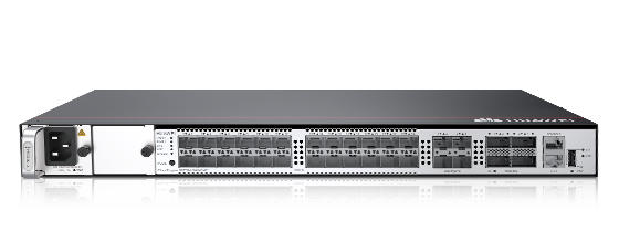
| Description | S5731-S48T4X-A (48*10/100/1000BASE-T ports, 4*10GE SFP+ ports, AC power) |
| Part Number | 98011854 |
| Model | S5731-S48T4X-A |
| First supported version | V200R021C10SPC500 |

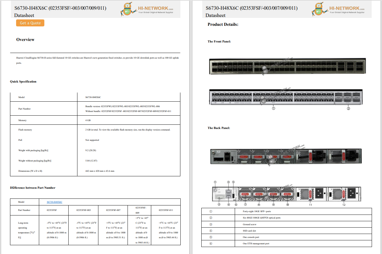
1 | Forty-eight 10/100/1000BASE-T ports | 2 | Four 10GE SFP+ ports |
3 | One console port | 4 | One ETH management port |
5 | One USB port | 6 | One PNP button NOTICE: To restore the factory settings and reset the switch, hold down the button for at least 6 seconds. To reset the switch, press the button. Resetting the switch will cause service interruption. Exercise caution when you press the PNP button. |
7 | Ground screw NOTE: It is used with a ground cable. | 8 | Jack for AC power cable locking strap NOTE: The AC power cable locking strap is not delivered with the switch. |
9 | AC socket NOTE: It is used with an AC power cable. | - | - |
| Port | Connector Type | Description | Available Components |
|---|---|---|---|
| 10/100/1000BASE-T port | RJ45 | A 10/100/1000BASE-T Ethernet electrical port sends and receives service data at 10/100/1000 Mbit/s. | Ethernet cable |
| 10GE SFP+ optical port | SFP+ | A 10GE SFP+ Ethernet optical port supports auto-sensing to 1000 Mbit/s. It sends and receives service data at 1000 Mbit/s or 10 Gbit/s. |
|
| Console port | RJ45 | The console port is connected to a console for on-site configuration. | Console cable |
| USB port | USB 2.0 Type A | The USB port can have a USB flash drive connected to upgrade the switch, or transfer configuration files or other files. The USB port can only connect to a USB flash drive that complies with USB 2.0. USB flash drives from different vendors differ in model compatibility and drivers. If a USB flash drive cannot be used, try to replace it with another one from a mainstream vendor. Switches support a maximum of 128 GB USB flash drives. | USB flash drive |
| ETH management port | RJ45 | You can connect a switch to a configuration terminal or network management workstation through the ETH management port to configure the switch locally or remotely. You can choose to download the software package through the ETH management port in the BootLoad menu. File transfer through the ETH management port is faster than transfer through the console port. | Ethernet cable |

No. | Indicator | Name | Color | Status | Description |
|---|---|---|---|---|---|
1 | PWR | Power module indicator | - | Off | The switch is powered off. |
Green | Steady on | The system power supply is normal. | |||
2 | SYS | System status indicator | - | Off | The system is not running. |
Green | Fast blinking | The system is starting. | |||
Green | Steady on | During the system startup preparation phase, the SYS indicator is steady green, which lasts for a maximum of 30 seconds. | |||
Green | Slow blinking | The system is running normally. | |||
Red | Steady on | The system does not work normally after registration, or a fan alarm or a temperature alarm has been generated. | |||
3 | MST | Stack indicator | - | Off |
|
Green | Steady on | The stack mode is selected. The switch is a standby or slave switch in a stack, and the service port indicators show the stack ID of the switch. | |||
Green | Blinking |
| |||
4 | SPEED | Speed indicator | - | Off | The speed mode is not selected. |
Green | Steady on | The speed mode is selected, and service port indicators show the speed of each port. | |||
5 | MODE | Mode switch button | - | - |
If you do not press the MODE button within 45 seconds, the service port indicators restore to the default mode. In this case, the SPEED indicator is off. NOTE: Hold down the mode switch button for 6s and release it to start the web initial login mode. Either of the following situations will occur:
|
6 | - | Electrical service port indicator (one indicator for each port) | Arrowheads show the positions of ports. A down arrowhead indicates a port at the bottom, and an up arrowhead indicates a port at the top. | Meanings of service port indicators vary in different modes. For details, see Table 4-1335 and Table 4-1336. | |
Optical service port indicator (two indicators for each port) | Each optical port has two single-color indicators. The one on the left is the ACT indicator (yellow), and the one on the right is the LINK indicator (green). Arrowheads show the positions of ports. A down arrowhead indicates a port at the bottom, and an up arrowhead indicates a port at the top. | ||||
7 | ID | ID indicator | - | Off | The ID indicator is not used (default state). |
Blue | Steady on | The indicator identifies the switch to maintain. The ID indicator can be turned on or off remotely to help field engineers find the switch to maintain. | |||
8 | L/A | ETH port indicator | - | Off | The ETH port is not connected. |
Green | Steady on | The ETH port is connected. | |||
Green | Blinking | The ETH port is sending or receiving data. | |||
9 | USB | USB-based deployment indicator | - | Off |
|
Green | Steady on | A USB-based deployment has been completed. | |||
Green | Blinking | The system is reading data from a USB flash drive. | |||
Yellow | Steady on | The switch has copied all the required files and completed the file check. The USB flash drive can be removed from the switch. | |||
Red | Blinking | An error has occurred when the system is executing the configuration file or reading data from the USB flash drive. | |||
Display Mode | Color | Status | Description |
|---|---|---|---|
Default mode | - | Off | The port is not connected or has been shut down. |
Green | Steady on | A link has been established on the port. | |
Green | Blinking | The port is sending or receiving data. | |
MST stack mode | - | Off | Port indicators do not show the stack ID of the switch. |
Green | Steady on | The switch is not the master switch in a stack.
| |
Green | Blinking | The switch is the master switch in a stack.
| |
Speed mode | - | Off | The port is not connected or has been shut down. |
Green | Steady on | 10M/100M/1000M port: The port is operating at 10 Mbit/s or 100 Mbit/s. | |
Green | Blinking | 10M/100M/1000M port: The port is operating at 1000 Mbit/s. |
Display Mode | Color | Status | Description |
|---|---|---|---|
Default mode (LINK indicator) | - | Off | The port is not connected or has been shut down. |
Green | Steady on | A link has been established on the port. | |
Default mode (ACT indicator) | - | Off | The port is not connected or has been shut down, or no data is transmitted or received. |
Yellow | Blinking | The port is sending or receiving data. | |
Speed mode (LINK indicator) | - | Off | The port is not connected or has been shut down. |
Green | Steady on | 1000M/10GE port: The port is operating at 1000 Mbit/s. | |
Green | Blinking | 1000M/10GE port: The port is operating at 10 Gbit/s. 1000M port: The port is operating at 1000 Mbit/s. |
The switch has a built-in AC power module and does not support pluggable power modules.
The switch has two built-in fans for forced air cooling. Air flows in from the left side and front panel, and exhausts from the right side.

This figure only shows the airflow direction and does not depict the actual device.
| Item | Specification |
|---|---|
| Dimensions without packaging (H x W x D) [mm(in.)] | Basic dimensions (excluding the parts protruding from the body): 43.6 mm x 442.0 mm x 220.0 mm (1.72 in. x 17.4 in. x 8.66 in.) Maximum dimensions (the depth is the distance from ports on the front panel to the parts protruding from the rear panel): 43.6 mm x 442.0 mm x 227.0 mm (1.72 in. x 17.4 in. x 8.94 in.) |
| Dimensions with packaging (H x W x D) [mm(in.)] | 90.0 mm x 550.0 mm x 355.0 mm (3.54 in. x 21.65 in. x 13.98 in.) |
| Chassis height [U] | 1 U |
| Chassis material | Metal |
| Weight without packaging [kg(lb)] | 3.21 kg (7.08 lb) |
| Weight with packaging [kg(lb)] | 4.57 kg (10.08 lb) |
| Typical power consumption [W] | 76 W |
| Typical heat dissipation [BTU/hour] | 259.32 BTU/hour |
| Maximum power consumption [W] | 102 W |
| Maximum heat dissipation [BTU/hour] | 348.03 BTU/hour |
| Static power consumption [W] | 48 W |
| MTBF [years] | 43.17 years |
| Availability | > 0.99999 |
| Noise at normal temperature (acoustic power) [dB(A)] | 44.90 dB(A) |
| Noise at normal temperature (acoustic pressure) [dB(A)] | 31.21 dB(A) |
| Number of card slots | 0 |
| Number of power slots | 0 |
| Number of fans modules | 2 |
| Redundant power supply | Not supported |
| Long-term operating temperature [°C(°F)] | -5°C to +50°C (23°F to 122°F) at an altitude of 0-1800 m (0-5905.44 ft.) |
| Restriction on the operating temperature variation rate [°C(°F)] | When the altitude is 1800-5000 m (5906-16404 ft.), the highest operating temperature reduces by 1°C (1.8°F) every time the altitude increases by 220 m (722 ft.). Devices cannot start when the temperature is lower than 0°C (32°F). The operating temperature of the switch is -5°C to +45°C (23°F to 113°F) when 10GE SFP+ optical modules with 40 km or longer transmission distances are used. |
| Storage temperature [°C(°F)] | -40°C to +70°C (-40°F to +158°F) |
| Long-term operating relative humidity [RH] | 5% RH to 95% RH, non-condensing |
| Long-term operating altitude [m(ft.)] | 0-5000 m (0-16404 ft.) |
| Storage altitude [m(ft.)] | 0-5000 m (0-16404 ft.) |
| Power supply mode | AC built-in |
| Rated input voltage [V] | AC input: 100 V AC to 240 V AC, 50/60 Hz |
| Input voltage range [V] | AC input: 90 V AC to 264 V AC, 47 Hz to 63 Hz |
| Maximum input current [A] | 3 A |
| Memory | 2 GB |
| Flash memory | 1 GB in total. To view the available flash memory size, run the display version command. |
| Console port | RJ45 |
| Eth Management port | RJ45 |
| USB | Supported |
| RTC | Supported |
| RPS input | Not supported |
| Service port surge protection [kV] | Common mode: ±7 kV |
| Power supply surge protection [kV] | ±6 kV in differential mode, ±6 kV in common mode |
| Ingress protection level (dustproof/waterproof) | IP20 |
| Types of fans | Built-in |
| Heat dissipation mode | Heat dissipation with fan, intelligent fan speed adjustment |
| Airflow direction | Air intake from left and front, air exhaustion from right |
| PoE | Not supported |
| Certification | EMC certification Safety certification Manufacturing certification |
| Item | Details |
|---|---|
| Description | S5731-S48T4X-A (48*10/100/1000BASE-T ports, 4*10GE SFP+ ports, AC power) |
| Part Number | 98011854-001 |
| Model | S5731-S48T4X-A |
| First supported version | V200R021C10SPC600 |
| Supported Patch Version | If V200R021C10SPC500 is used, install V200R021HP0121 or a later patch. |

1 | Forty-eight 10/100/1000BASE-T ports | 2 | Four 10GE SFP+ ports |
3 | One console port | 4 | One ETH management port |
5 | One USB port | 6 | One PNP button NOTICE: To restore the factory settings and reset the switch, hold down the button for at least 6 seconds. To reset the switch, press the button. Resetting the switch will cause service interruption. Exercise caution when you press the PNP button. |
7 | Ground screw NOTE: It is used with a ground cable. | 8 | Jack for AC power cable locking strap NOTE: The AC power cable locking strap is not delivered with the switch. |
9 | AC socket NOTE: It is used with an AC power cable. | - | - |
| Port | Connector Type | Description | Available Components |
|---|---|---|---|
| 10/100/1000BASE-T port | RJ45 | A 10/100/1000BASE-T Ethernet electrical port sends and receives service data at 10/100/1000 Mbit/s. | Ethernet cable |
| 10GE SFP+ optical port | SFP+ | A 10GE SFP+ Ethernet optical port supports auto-sensing to 1000 Mbit/s. It sends and receives service data at 1000 Mbit/s or 10 Gbit/s. |
|
| Console port | RJ45 | The console port is connected to a console for on-site configuration. | Console cable |
| USB port | USB 2.0 Type A | The USB port can have a USB flash drive connected to upgrade the switch, or transfer configuration files or other files. The USB port can only connect to a USB flash drive that complies with USB 2.0. USB flash drives from different vendors differ in model compatibility and drivers. If a USB flash drive cannot be used, try to replace it with another one from a mainstream vendor. Switches support a maximum of 128 GB USB flash drives. | USB flash drive |
| ETH management port | RJ45 | You can connect a switch to a configuration terminal or network management workstation through the ETH management port to configure the switch locally or remotely. You can choose to download the software package through the ETH management port in the BootLoad menu. File transfer through the ETH management port is faster than transfer through the console port. | Ethernet cable |

No. | Indicator | Name | Color | Status | Description |
|---|---|---|---|---|---|
1 | PWR | Power module indicator | - | Off | The switch is powered off. |
Green | Steady on | The system power supply is normal. | |||
2 | SYS | System status indicator | - | Off | The system is not running. |
Green | Fast blinking | The system is starting. | |||
Green | Steady on | During the system startup preparation phase, the SYS indicator is steady green, which lasts for a maximum of 30 seconds. | |||
Green | Slow blinking | The system is running normally. | |||
Red | Steady on | The system does not work normally after registration, or a fan alarm or a temperature alarm has been generated. | |||
3 | MST | Stack indicator | - | Off |
|
Green | Steady on | The stack mode is selected. The switch is a standby or slave switch in a stack, and the service port indicators show the stack ID of the switch. | |||
Green | Blinking |
| |||
4 | SPEED | Speed indicator | - | Off | The speed mode is not selected. |
Green | Steady on | The speed mode is selected, and service port indicators show the speed of each port. | |||
5 | MODE | Mode switch button | - | - |
If you do not press the MODE button within 45 seconds, the service port indicators restore to the default mode. In this case, the SPEED indicator is off. NOTE: Hold down the mode switch button for 6s and release it to start the web initial login mode. Either of the following situations will occur:
|
6 | - | Electrical service port indicator (one indicator for each port) | Arrowheads show the positions of ports. A down arrowhead indicates a port at the bottom, and an up arrowhead indicates a port at the top. | Meanings of service port indicators vary in different modes. For details, see Table 4-1341 and Table 4-1342. | |
Optical service port indicator (two indicators for each port) | Each optical port has two single-color indicators. The one on the left is the ACT indicator (yellow), and the one on the right is the LINK indicator (green). Arrowheads show the positions of ports. A down arrowhead indicates a port at the bottom, and an up arrowhead indicates a port at the top. | ||||
7 | ID | ID indicator | - | Off | The ID indicator is not used (default state). |
Blue | Steady on | The indicator identifies the switch to maintain. The ID indicator can be turned on or off remotely to help field engineers find the switch to maintain. | |||
8 | L/A | ETH port indicator | - | Off | The ETH port is not connected. |
Green | Steady on | The ETH port is connected. | |||
Green | Blinking | The ETH port is sending or receiving data. | |||
9 | USB | USB-based deployment indicator | - | Off |
|
Green | Steady on | A USB-based deployment has been completed. | |||
Green | Blinking | The system is reading data from a USB flash drive. | |||
Yellow | Steady on | The switch has copied all the required files and completed the file check. The USB flash drive can be removed from the switch. | |||
Red | Blinking | An error has occurred when the system is executing the configuration file or reading data from the USB flash drive. | |||
Display Mode | Color | Status | Description |
|---|---|---|---|
Default mode | - | Off | The port is not connected or has been shut down. |
Green | Steady on | A link has been established on the port. | |
Green | Blinking | The port is sending or receiving data. | |
MST stack mode | - | Off | Port indicators do not show the stack ID of the switch. |
Green | Steady on | The switch is not the master switch in a stack.
| |
Green | Blinking | The switch is the master switch in a stack.
| |
Speed mode | - | Off | The port is not connected or has been shut down. |
Green | Steady on | 10M/100M/1000M port: The port is operating at 10 Mbit/s or 100 Mbit/s. | |
Green | Blinking | 10M/100M/1000M port: The port is operating at 1000 Mbit/s. |
Display Mode | Color | Status | Description |
|---|---|---|---|
Default mode (LINK indicator) | - | Off | The port is not connected or has been shut down. |
Green | Steady on | A link has been established on the port. | |
Default mode (ACT indicator) | - | Off | The port is not connected or has been shut down, or no data is transmitted or received. |
Yellow | Blinking | The port is sending or receiving data. | |
Speed mode (LINK indicator) | - | Off | The port is not connected or has been shut down. |
Green | Steady on | 1000M/10GE port: The port is operating at 1000 Mbit/s. | |
Green | Blinking | 1000M/10GE port: The port is operating at 10 Gbit/s. 1000M port: The port is operating at 1000 Mbit/s. |
The switch has a built-in AC power module and does not support pluggable power modules.
The switch has two built-in fans for forced air cooling. Air flows in from the left side and front panel, and exhausts from the right side.

This figure only shows the airflow direction and does not depict the actual device.
| Item | Specification |
|---|---|
| Dimensions without packaging (H x W x D) [mm(in.)] | Basic dimensions (excluding the parts protruding from the body): 43.6 mm x 442.0 mm x 220.0 mm (1.72 in. x 17.4 in. x 8.66 in.) Maximum dimensions (the depth is the distance from ports on the front panel to the parts protruding from the rear panel): 43.6 mm x 442.0 mm x 227.0 mm (1.72 in. x 17.4 in. x 8.94 in.) |
| Dimensions with packaging (H x W x D) [mm(in.)] | 90.0 mm x 550.0 mm x 355.0 mm (3.54 in. x 21.65 in. x 13.98 in.) |
| Chassis height [U] | 1 U |
| Chassis material | Metal |
| Weight without packaging [kg(lb)] | 3.21 kg (7.08 lb) |
| Weight with packaging [kg(lb)] | 4.57 kg (10.08 lb) |
| Typical power consumption [W] | 76 W |
| Typical heat dissipation [BTU/hour] | 259.32 BTU/hour |
| Maximum power consumption [W] | 102 W |
| Maximum heat dissipation [BTU/hour] | 348.03 BTU/hour |
| Static power consumption [W] | 48 W |
| MTBF [years] | 43.17 years |
| Availability | > 0.99999 |
| Noise at normal temperature (acoustic power) [dB(A)] | 44.90 dB(A) |
| Noise at normal temperature (acoustic pressure) [dB(A)] | 31.21 dB(A) |
| Number of card slots | 0 |
| Number of power slots | 0 |
| Number of fans modules | 2 |
| Redundant power supply | Not supported |
| Long-term operating temperature [°C(°F)] | -5°C to +50°C (23°F to 122°F) at an altitude of 0-1800 m (0-5905.44 ft.) |
| Restriction on the operating temperature variation rate [°C(°F)] | When the altitude is 1800-5000 m (5906-16404 ft.), the highest operating temperature reduces by 1°C (1.8°F) every time the altitude increases by 220 m (722 ft.). Devices cannot start when the temperature is lower than 0°C (32°F). The operating temperature of the switch is -5°C to +45°C (23°F to 113°F) when 10GE SFP+ optical modules with 40 km or longer transmission distances are used. |
| Storage temperature [°C(°F)] | –40°C to +70°C (–40°F to +158°F) |
| Long-term operating relative humidity [RH] | 5% RH to 95% RH, non-condensing |
| Long-term operating altitude [m(ft.)] | 0–5000 m (0–16404 ft.) |
| Storage altitude [m(ft.)] | 0-5000 m (0-16404 ft.) |
| Power supply mode | AC built-in |
| Rated input voltage [V] | AC input: 100–240 V AC; 50/60 Hz |
| Input voltage range [V] | AC input: 90 V AC to 264 V AC, 47 Hz to 63 Hz |
| Maximum input current [A] | 3 A |
| Memory | 2 GB |
| Flash memory | 1 GB in total. To view the available flash memory size, run the display version command. |
| Console port | RJ45 |
| Eth Management port | RJ45 |
| USB | Supported |
| RTC | Supported |
| RPS input | Not supported |
| Service port surge protection [kV] | Common mode: ±7 kV |
| Power supply surge protection [kV] | Differential mode: ±6 kV; common mode: ±6 kV |
| Ingress protection level (dustproof/waterproof) | IP20 |
| Types of fans | Built-in |
| Heat dissipation mode | Air cooling for heat dissipation, intelligent fan speed adjustment |
| Airflow direction | Air intake from left and front, air exhaustion from right |
| PoE | Not supported |
| Certification | EMC certification Safety certification Manufacturing certification |
 Hot Tags :
Huawei Switches
hot products
Hot Tags :
Huawei Switches
hot products
Register Email now for Weekly Promotion Stock
100% free, Unsubscribe any time!
Add 1: Room 605 6/F FA YUEN Commercial Building, 75-77 FA YUEN Street, Mongkok KL, HongKong Add 2: Room 405, Building E, MeiDu Building, Gong Shu District, Hangzhou City, Zhejiang Province, China
Whatsapp/Tel: +8618057156223 Tel: 0086 571 86729517 Tel in HK: 00852 66181601
Email: [email protected]
 English
 Pусский
 Français
 Español
 Português