Register now for better personalized quote!

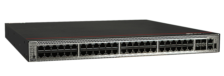
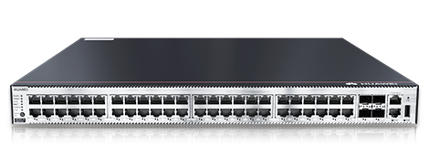
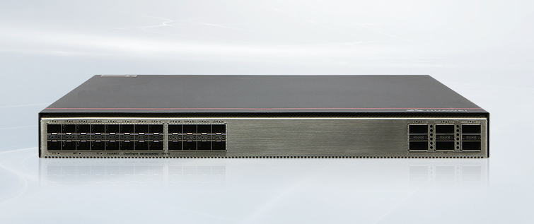
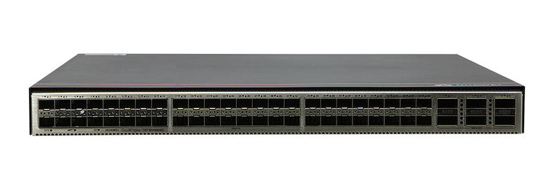
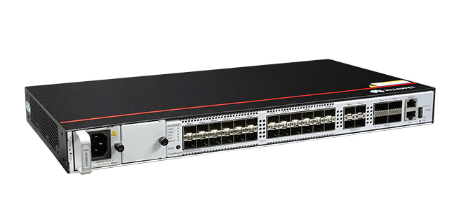
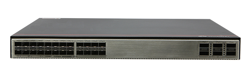
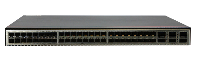
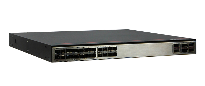
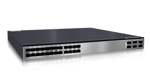
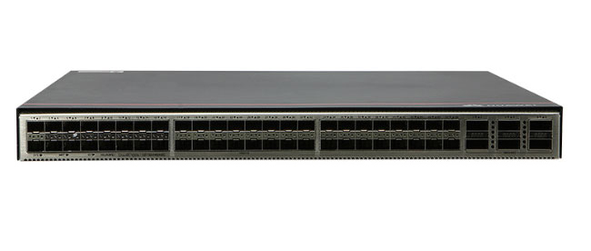


The Huawei S5731-S48P4X is a PoE (Power over Ethernet) switch featuring 48 10/100/1000BASE-T ports and 4 10GE SFP+ ports. It supports two power module slots, each accommodating either a 1000 W or 600 W PoE power module, enabling flexible power configurations to meet various networking requirements.
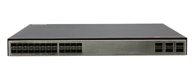
▪ Port Configuration: The switch offers 48 Gigabit Ethernet ports for high-speed connectivity and 4 10-Gigabit SFP+ uplink ports, ensuring robust data transmission capabilities.
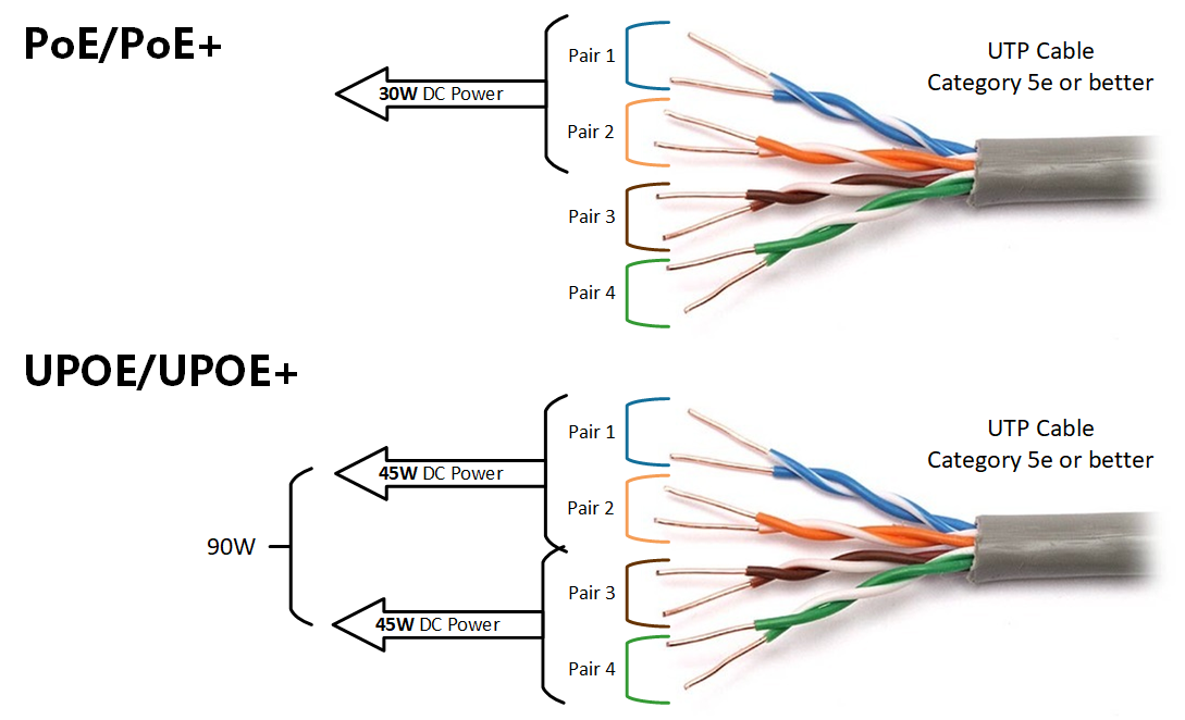
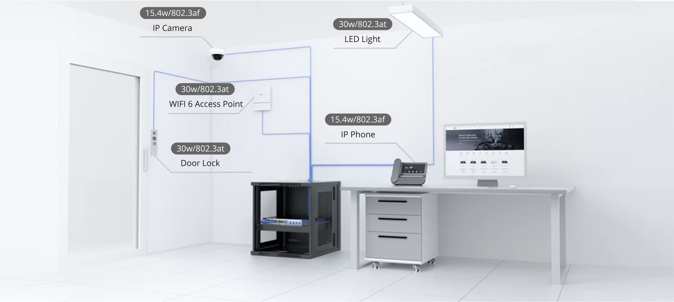
▪ PoE Support: With PoE+ capabilities, the S5731-S48P4X can deliver power to connected devices such as IP phones, wireless access points, and IP cameras, simplifying network deployment and reducing the need for additional power sources.
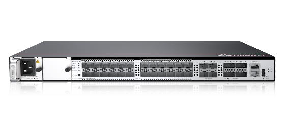
▪ Power Module Slots: The device includes two slots for power modules, allowing for the installation of either 1000 W or 600 W PoE power modules. This flexibility supports various power requirements and enhances the scalability of the network infrastructure.
▪ Cooling System: The switch is equipped with fan modules to maintain optimal operating temperatures. Compatible fan modules include the FAN-023A-B, which is a fan box designed for side exhaust.
INFO.
▪ Memory and Storage: The S5731-S48P4X comes with 2 GB of memory and a total of 1 GB flash memory, ensuring efficient performance and adequate storage for configurations and system files.
INFO.
▪ Optical Modules: The switch supports various optical modules for the 10GE SFP+ ports, providing flexibility in network design and implementation. Specific compatible optical modules can be found in Huawei's technical documentation.
INFO.
▪ Fan Modules: As mentioned, the FAN-023A-B is a compatible fan module, ensuring proper cooling and reliable operation of the switch.
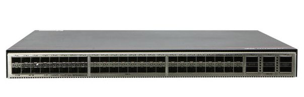
Huawei CloudEngine Switch S5731-S48P4X
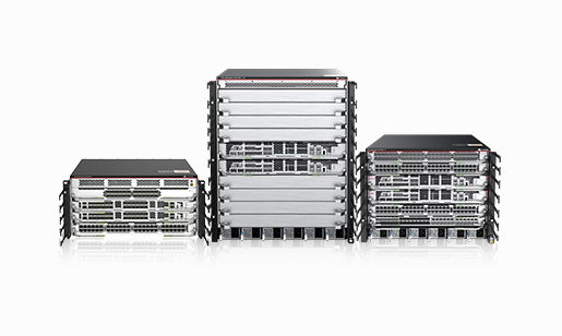
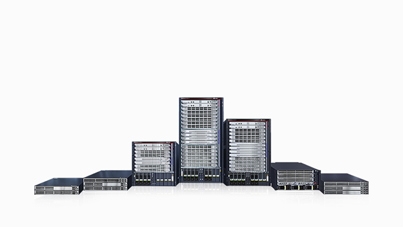
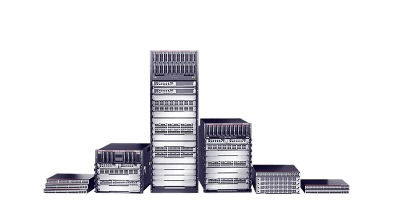
Huawei All Series Switches New and Used
For Huawei product list and quote, please visit: https://www.hi-network.com/categories/huawei or contact us at www.hi-network.com (Email: [email protected])
Table 4-1344 lists the mapping between the S5731-S48P4X chassis and software versions.


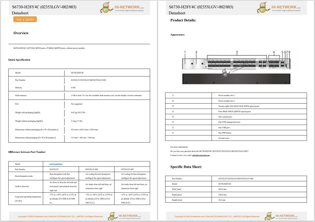
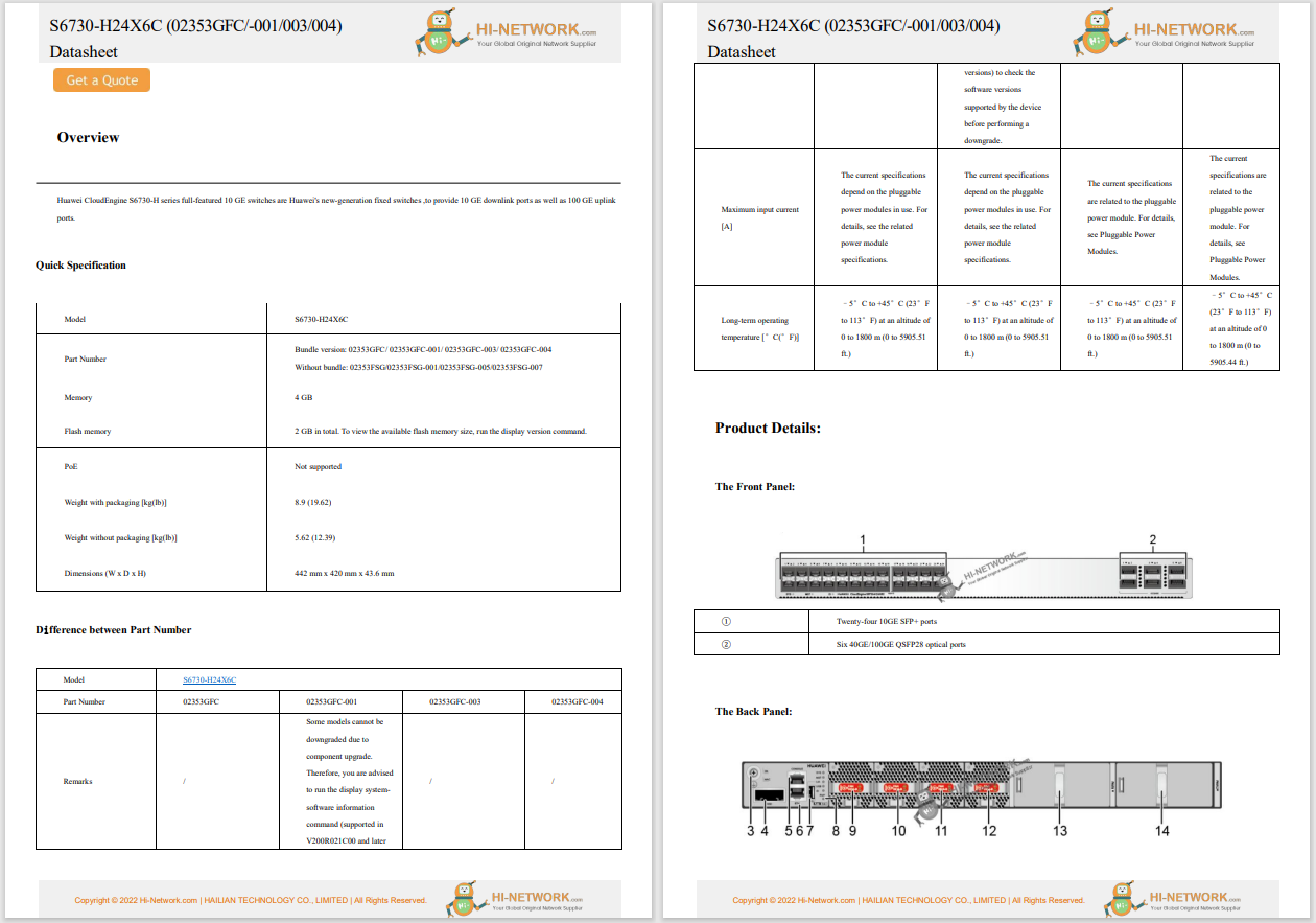
1 | Forty-eight PoE+ 10/100/1000BASE-T ports | 2 | Four 10GE SFP+ ports Applicable modules and cables:
|
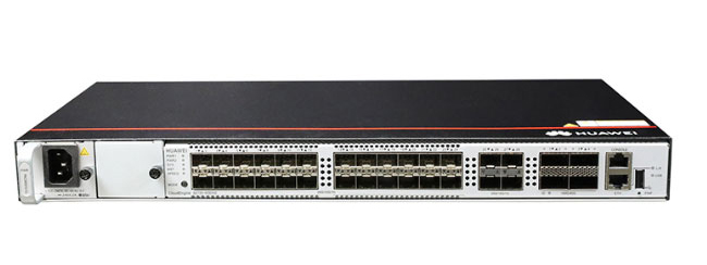
3 | One console port | 4 | One ETH management port |
5 | One USB port | 6 | One PNP button NOTICE: To restore the factory settings and reset the switch, hold down the button for at least 6 seconds. To reset the switch, press the button. Resetting the switch will cause service interruption. Exercise caution when you press the PNP button. |
7 | Ground screw NOTE: It is used with a ground cable. | 8 | Fan module slot 1 NOTE: Applicable fan module: FAN-023A-B (Fan Box (B, Fan Panel Side Exhaust)) |
9 | Fan module slot 2 NOTE: Applicable fan module: FAN-023A-B (Fan Box (B, Fan Panel Side Exhaust)) | 10 | Power module slot 1 NOTE: Applicable power module:
|
11 | Power module slot 2 NOTE: Applicable power module:
| - | - |
10/100/1000BASE-T port
10GE SFP+ optical port
Console port
ETH management port
Attribute | Description |
|---|---|
Connector type | RJ45 |
Standards compliance | IEEE802.3 |
Working Mode | 10/100 Mbit/s auto-sensing |
Maximum transmission distance | 100 m |
USB port

USB flash drives from different vendors differ in model compatibility and drivers. If a USB flash drive cannot be used, try to replace it with another one from a mainstream vendor. Switches support a maximum of 128 GB USB flash drives.
If the switch has no configuration file, the system attempts to enter the web initial login mode. In this mode, the status of mode indicators is as follows:
If the system enters the web initial login mode successfully, all mode indicators turn green and stay on for a maximum of 10 minutes.
If the system fails to enter the initial login mode, all mode indicators fast blink for 10 seconds and then restore the default status.
If the switch has a configuration file, the system cannot enter the web initial login mode. In this case, all mode indicators fast blink for 10s, and then return to the default states.


No. | Indicator | Name | Color | Status | Description |
|---|---|---|---|---|---|
1 | PWR1 | Power module indicator | - | Off | No power module is available in power module slot 1, or the switch has only one power module but the power module does not work normally. |
Green | Steady on | A power module is installed in power module slot 1 and is working normally. | |||
Yellow | Steady on | The switch has two power modules installed. Any of the following situations occurs in power module slot 1:
| |||
2 | PWR2 | Power module indicator | - | Off | No power module is available in power module slot 2, or the switch has only one power module but the power module does not work normally. |
Green | Steady on | A power module is installed in power module slot 2 and is working normally. | |||
Yellow | Steady on | The switch has two power modules installed. Any of the following situations occurs in power module slot 2:
| |||
3 | SYS | System status indicator | - | Off | The system is not running. |
Green | Fast blinking | The system is starting. | |||
Green | Steady on | During the system startup preparation phase, the SYS indicator is steady green, which lasts for a maximum of 30 seconds. | |||
Green | Slow blinking | The system is running normally. | |||
Red | Steady on | The system does not work normally after registration, or a fan alarm or a temperature alarm has been generated. | |||
4 | MST | Stack indicator | - | Off |
|
Green | Steady on | The stack mode is selected. The switch is a standby or slave switch in a stack, and the service port indicators show the stack ID of the switch. | |||
Green | Blinking |
| |||
5 | SPEED | Speed indicator | - | Off | The speed mode is not selected. |
Green | Steady on | The speed mode is selected, and service port indicators show the speed of each port. | |||
6 | PoE | PoE indicator | - | Off | The PoE mode is not selected. |
Green | Steady on | The PoE mode is selected, and service port indicators show the PoE status of each port. | |||
7 | MODE | Mode switch button | - | - |
If you do not press the MODE button within 45 seconds, the service port indicators restore to the default mode. In this case, the SPEED and PoE indicators are off. |
ID | ID indicator NOTE: The mode switch button on the 02353AJH has an ID indicator. | - | Off | The ID indicator is not used (default state). | |
Blue | Steady on | The indicator identifies the switch to maintain. The ID indicator can be turned on or off remotely to help field engineers find the switch to maintain. | |||
8 | - | Electrical service port indicator (one indicator for each port) | The indicator in the upper left corner of a port indicates the indicator of a port at the top, and the indicator in the upper right corner indicates the indicator of a port at the bottom. | Meanings of service port indicators vary in different modes. For details, see Table 4-1350 and Table 4-1351. | |
Optical service port indicator (two indicators for each port) | Each optical port has two single-color indicators. The one on the left is the ACT indicator (yellow), and the one on the right is the LINK indicator (green). Arrowheads show the positions of ports. A down arrowhead indicates a port at the bottom, and an up arrowhead indicates a port at the top. | ||||
9 | ETH | ETH port indicator | - | Off | The ETH port is not connected. |
Green | Steady on | The ETH port is connected. | |||
Green | Blinking | The ETH port is sending or receiving data. | |||
10 | - | USB-based deployment indicator | - | Off |
|
Green | Steady on | A USB-based deployment has been completed. | |||
Green | Blinking | The system is reading data from a USB flash drive. | |||
Yellow | Steady on | The switch has copied all the required files and completed the file check. The USB flash drive can be removed from the switch. | |||
Red | Blinking | An error has occurred when the system is executing the configuration file or reading data from the USB flash drive. | |||
Display Mode | Color | Status | Description |
|---|---|---|---|
Default mode | - | Off | The port is not connected or has been shut down. |
Green | Steady on | A link has been established on the port. | |
Green | Blinking | The port is sending or receiving data. | |
MST stack mode | Green | Off | Port indicators do not show the stack ID of the switch. |
Steady on | The switch is not the master switch in a stack.
| ||
Blinking | The switch is the master switch in a stack.
| ||
Speed mode | - | Off | The port is not connected or has been shut down. |
Green | Steady on | 10M/100M/1000M port: The port is operating at 10 Mbit/s or 100 Mbit/s. | |
Green | Blinking | 10M/100M/1000M port: The port is operating at 1000 Mbit/s. | |
PoE mode | - | Off | The port is not providing power to a powered device (PD). |
Green | Steady on | The port is providing power to a PD. | |
Green | Blinking | The power of the PD connected to the port exceeds the power capacity of the port or the power threshold configured on the port. Alternatively, the PD does not comply with IEEE standards. |
Display Mode | Color | Status | Description |
|---|---|---|---|
Default mode | - | Off | The port is not connected or has been shut down. |
Green | Steady on | A link has been established on the port. | |
Yellow | Blinking | The port is sending or receiving data. | |
Speed mode | - | Off | The port is not connected or has been shut down. |
Green | Steady on | 1000M/10GE port: The port is operating at 1000 Mbit/s. | |
Green | Blinking | 1000M/10GE port: The port is operating at 10 Gbit/s. 1000M port: The port is operating at 1000 Mbit/s. |
The switch is a PoE switch and supports two power module slots, each of which can have a 1000 W PoE or 600 W PoE power module installed. Pluggable AC and DC PoE power modules can be used together in the same switch.
Power Module 1 | Power Module 2 | Available PoE Power | Maximum Number of Ports (Fully Loaded) |
|---|---|---|---|
1000 W AC (220 V) 1000 W DC | – | 760 W |
|
1000 W AC (110 V) | – | 665 W |
|
1000 W AC (220 V) 1000 W DC | 1000 W AC (220 V) 1000 W DC | 1600 W |
|
1000 W AC (110 V) 1000 W DC | 1000 W AC (110 V) | Versions earlier than V200R021C10: 1330 W V200R021C10 and later versions: 1520 W |
|
600 W AC (220 V) | – | 380 W |
|
600 W AC (110 V) | – | 95 W |
|
600 W AC (220 V) | 600 W AC (220 V) | 950 W |
|
600 W AC (110 V) | 600 W AC (110 V) | 380 W |
|
1000 W AC (220 V) 1000 W DC | 600 W AC (220 V) | 1330 W |
|
When a switch has two power modules installed, the two power modules work in redundancy mode to provide power for the chassis and in load balancing mode to provide power for PDs.
The S5731-S48P4X uses pluggable fan modules for forced air cooling. Air flows in from the front side and exhausts from the rear panel.
This figure only shows the airflow direction and does not depict the actual device.
Table 4-1353 lists technical specifications of the S5731-S48P4X.
Item | Description |
|---|---|
Memory (RAM) | 2 GB |
Flash | 1 GB in total. To view the available flash memory size, run the display version command. |
Mean time between failures (MTBF) | 54.96 years |
Mean time to repair (MTTR) | 2 hours |
Availability | > 0.99999 |
Service port surge protection | Common mode: ±6 kV |
Power supply surge protection |
|
Dimensions (H x W x D) |
|
Weight (with packaging) | 8.8 kg (19.40 lb) |
Stack ports | 10GE SFP+ ports on the front panel |
RTC | Supported |
RPS | Not supported |
PoE | Supported |
Rated voltage range |
|
Maximum voltage range |
|
Maximum power consumption (100% throughput, full speed of fans) |
|
Typical power consumption (30% of traffic load, tested according to ATIS standard) | 108 W |
Operating temperature | -5°C to +45°C (23°F to 113°F) at an altitude of 0-1800 m (0-5906 ft.) NOTE: When the altitude is 1800-5000 m (5906-16404 ft.), the highest operating temperature reduces by 1°C (1.8°F) every time the altitude increases by 220 m (722 ft.). The switch cannot be started when the ambient temperature is lower than 0°C (32°F). |
Storage temperature | -40°C to +70°C (-40°F to +158°F) |
Noise under normal temperature (27°C, sound power) | < 62.3 dB(A) |
Relative humidity | 5% to 95%, noncondensing |
Operating altitude | 0-5000 m (0-16404 ft.) |
Certification |
|
Part number | 02353AJH 02353AJH-001 02353AJH-003 |
 Hot Tags :
Huawei Switches
hot products
Hot Tags :
Huawei Switches
hot products
Register Email now for Weekly Promotion Stock
100% free, Unsubscribe any time!
Add 1: Room 605 6/F FA YUEN Commercial Building, 75-77 FA YUEN Street, Mongkok KL, HongKong Add 2: Room 405, Building E, MeiDu Building, Gong Shu District, Hangzhou City, Zhejiang Province, China
Whatsapp/Tel: +8618057156223 Tel: 0086 571 86729517 Tel in HK: 00852 66181601
Email: [email protected]
 English
 Pусский
 Français
 Español
 Português