




Route reflectors have become an important part of any larger internet service provider's setup. Nowadays, it is difficult to imagine having multiple routers running BGP in a full mesh topology due to scalability concerns. The concept of route reflectors can be found in RFC4456, which was published in 2006. It is crucial to have a good understanding of the BGP protocol before working with route reflectors.
So, why are route reflectors so helpful for scalability? To answer this question, let's first look at how routes exchange information through the BGP protocol. In external BGP (when connecting different autonomous systems), there is a simple solution to avoid routing loops by using the autonomous system number, which indicates the origin of each route. When a router sees its own AS number in a route, it knows that it is coming from its own autonomous system and does not use it to prevent a loop. This mechanism works well for internet routes (eBGP), but it limits scalability with internal BGP peerings (iBGP). Since the AS number for iBGP peers is the same, the BGP protocol had to adopt a special rule. None of the routes received from one iBGP peer can be advertised or forwarded to another iBGP peer. In simple terms, all iBGP peers need to establish a neighborship with every other iBGP router, which results in a large number of BGP sessions.
This is the formula for calculating the number of sessions needed for a full mesh:
N(N -1)/2 [where N represents number of routers]
For 20 routers for instance: 20(20-1)/2 = 190 BGP sessions
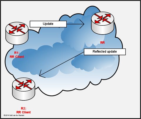
Route reflector explained

iBGP full mesh topology
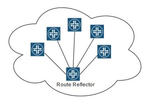
iBGP topology with route reflector
A Route reflector is like a central hub for all the iBGP routers. It helps in sharing routing information among these routers. It can send routes to other routers within the network.
This makes it easier to manage a large BGP network. It is recommended to have at least two route reflectors working together as a backup in case one of them fails. This is called a cluster and it ensures that the route reflector, which is an important component, remains functional even if one fails.
Route reflector configuration
We have set up a basic situation with one main router and two connected routers. All routers are running Cisco IOS. The Ethernet connections are set up with small networks within the private IP range of 10.0.0.0. Additionally, loopback interfaces are used for internal BGP connections.
R1 – 192.168.1.1
R2 – 192.168.2.1
RR – 192.168.0.3
We utilized the RIP protocol to share details about all IP prefixes and loopback interfaces. Specifically, the interface loopback-50 on R1 (IP 50.50.50.50) will only be promoted through the BGP protocol to ensure the proper functioning of our network structure. R1 will advertise its Loopback50 to the route reflector, which will then further advertise it to R2.
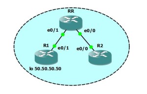
Topology with one route reflector in GNS3
Configuring route reflectors on Cisco devices
R1#show run | s bgp| s rip| s bgp| s rip| s bgp| s ripint eth 0/1
interface Ethernet0/1
ip address 10.0.0.1 255.255.255.252
full-duplex
end
R1#show run int lo 0
interface Loopback0
ip address 192.168.1.1 255.255.255.255
end
R1#show run int lo 50
interface Loopback50
ip address 50.50.50.50 255.255.255.0
end
R1#show run | s rip
router rip
network 10.0.0.0
network 192.168.1.0
no auto-summary
R1#show run | s bgp
router bgp 100
no synchronization
bgp log-neighbor-changes
network 50.50.50.0 mask 255.255.255.0
neighbor 192.168.0.3 remote-as 100
neighbor 192.168.0.3 update-source Loopback0
no auto-summary
R2#show run int e0/0
interface Ethernet0/0
ip address 10.0.0.6 255.255.255.255
full-duplex
end
R2#show run int lo0
interface Loopback0
ip address 192.168.2.1 255.255.255.255
end
R2#show run | s rip
router rip
network 10.0.0.0
network 192.168.2.0
no auto-summary
R2#show run | s bgp
router bgp 10
no synchronizatio
bgp log-neighbor-changes
neighbor 192.168.0.3 remote-as 100
neighbor 192.168.0.3 update-source Loopback0
no auto-summary
RR#show run int eth 0/1
interface Ethernet0/1
ip address 10.0.0.2 255.255.255.252
full-duplex
end
RR#show run int eth 0/0
interface Ethernet0/0
ip address 10.0.0.5 255.255.255.252
full-duplex
end
RR#show run int lo0
interface Loopback0
ip address 192.168.0.3 255.255.255.255
end
RR#show run | s rip
router rip
network 10.0.0.0
network 192.168.0.0
no auto-summary
RR#show run | s bgp
router bgp 100
no synchronization
bgp log-neighbor-changes
neighbor 192.168.1.1 remote-as 100
neighbor 192.168.1.1 update-source Loopback0
neighbor 192.168.1.1 route-reflector-client
neighbor 192.168.2.1 remote-as 100
neighbor 192.168.2.1 update-source Loopback0
neighbor 192.168.2.1 route-reflector-client
no auto-summary
Now we need to test that we can reach the Loopback 50 from R2, so let’s verify its routing table first:
R2#show ip route
***
50.0.0.0/24 is subnetted, 1 subnets
B 50.50.50.0 [200/0] via 192.168.1.1, 00:14:12
10.0.0.0/30 is subnetted, 2 subnets
R 10.0.0.0 [120/1] via 10.0.0.5, 00:00:07, Ethernet0/0
C 10.0.0.4 is directly connected, Ethernet0/0
R 192.168.0.0/24 [120/1] via 10.0.0.5, 00:00:07, Ethernet0/0
R 192.168.1.0/24 [120/1] via 10.0.0.5, 00:00:07, Ethernet0/0
192.168.2.0/32 is subnetted, 1 subnets
C 192.168.2.1 is directly connected, Loopback0
R2#ping 50.50.50.50
Type escape sequence to abort.
Sending 5, 100-byte ICMP Echos to 50.50.50.50, timeout is 2 seconds:
!!!!!
Success rate is 100 percent (5/5), round-trip min/avg/max = 32/56/76 ms
Great, we can see the path to the 50.50.50.0 network in R2's routing table, and it shows that we can reach it. If we want toadd another iBGP router, we just have to establish a connection with the route reflector and obtain all the networks. However, we must remember to advertise it by using the network command in the R1 configuration. It's important to note that Cisco routers don't automatically advertise anything.
If you need Switches, Routers, or need more network information, welcome to contact us www.hi-network.com (Email: info@hi-network.com)
 Hot Tags :
CISCO
router